No products in the cart.

All rights of this website are reserved for EXTRUTEX Austria and its partner companies, © 2026

Multiple Payment Methods

Discount for advance payments over 50%

Free Shipping Coordination Services
Payment methods:


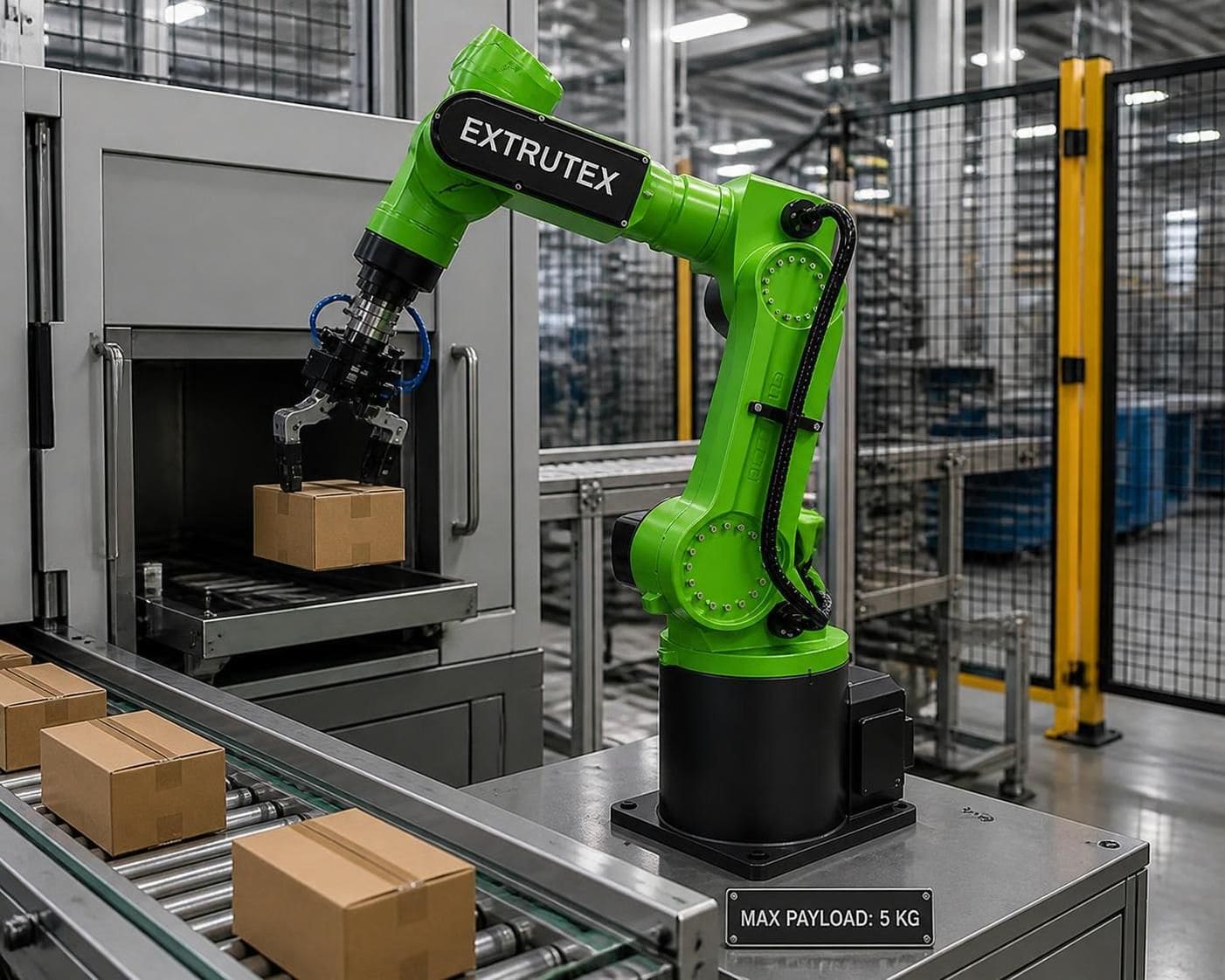
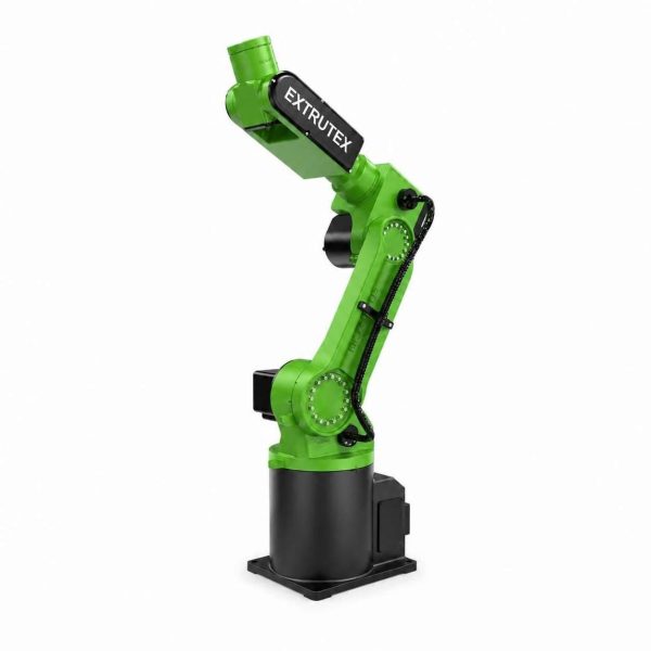
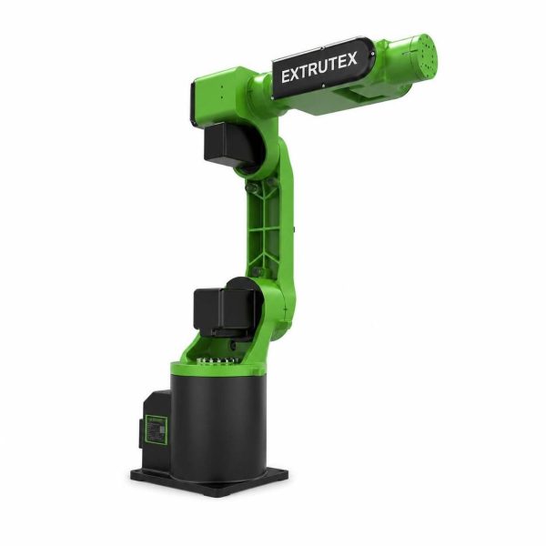
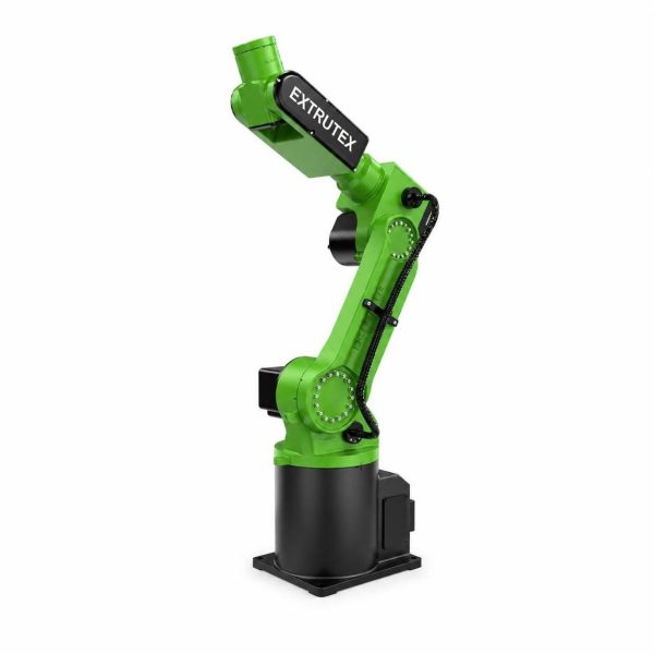
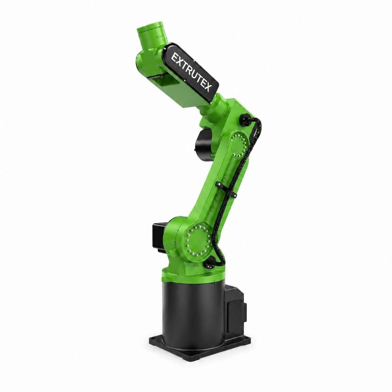
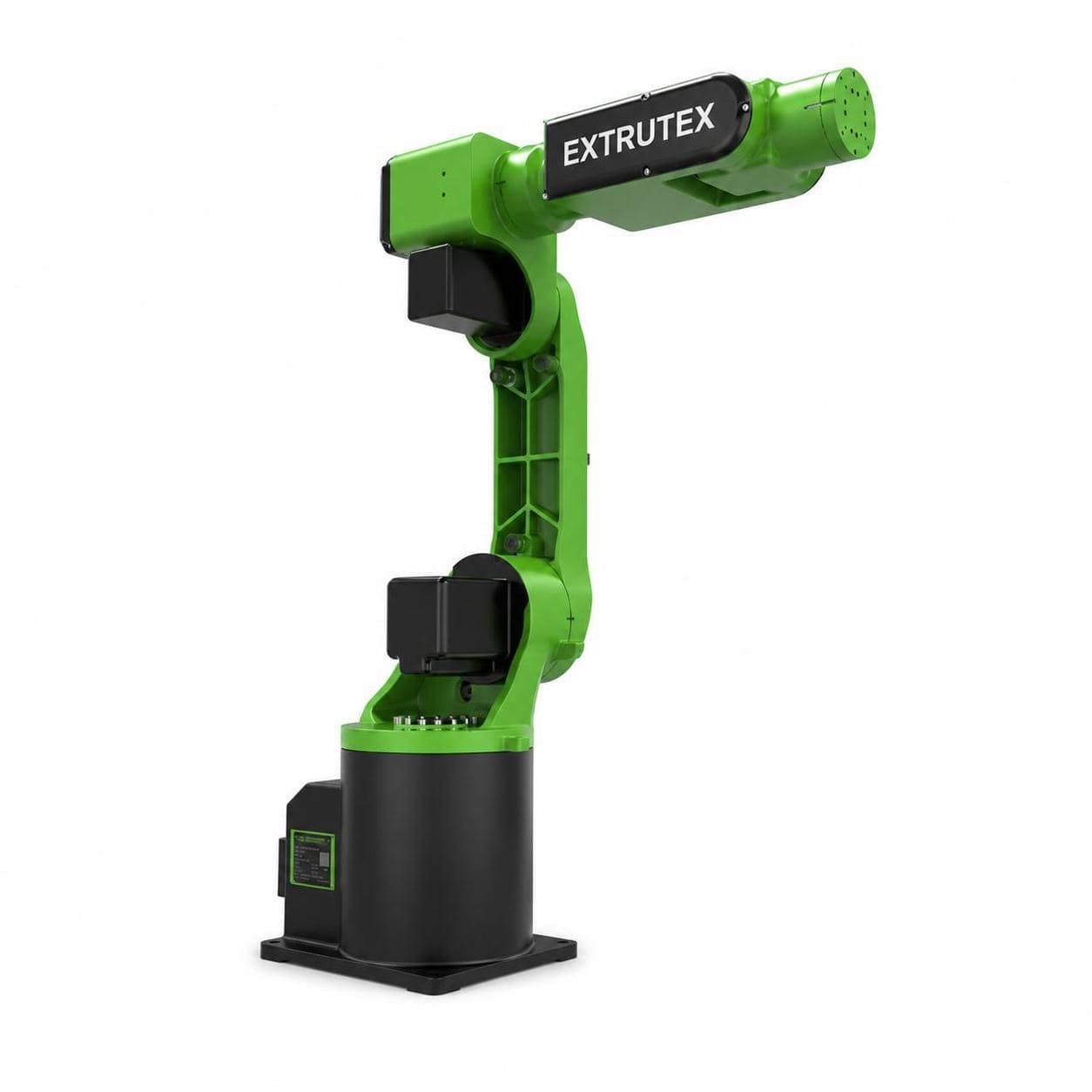
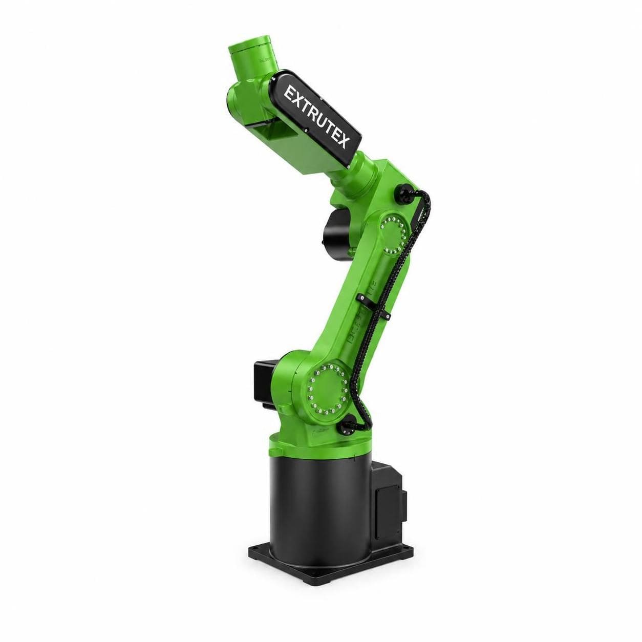
The EXTRUTEX EX-FR05 Six-Axis Compact Industrial Robot is a compact industrial automation solution developed for flexible handling, precision positioning, component transfer, machine tending, assembly and repetitive production operations. With six independently controlled axes, a nominal arm length of 990 mm, a maximum rated payload of 5 kg and published repeatability of ±0.05 mm, this robotic platform is suitable for manufacturers seeking to automate repetitive tasks without installing a large industrial robot.
Designed around an articulated mechanical structure and electric servo-driven motion, the EX-FR05 can move workpieces through multiple orientations and approach positions. Its six degrees of freedom allow the wrist and end effector to be positioned at different angles, making it useful for applications where a simple linear transfer mechanism or conventional three-axis manipulator cannot provide sufficient flexibility.
EXTRUTEX positions the EX-FR05 as a compact automation option for plastics processing, injection molding, packaging, light assembly, material handling and general industrial production. When integrated with suitable grippers, sensors, fixtures and machine controls, the robot can help improve production consistency, reduce repetitive manual work and create a more organized manufacturing workflow.
The EX-FR05 belongs to the articulated six-axis industrial robot category. Its mechanical system combines a rotating base, articulated arm sections and a multi-axis wrist. Each joint contributes a different movement, allowing the end effector to reach a workpiece from different directions within the robot's permitted working envelope.
Unlike a basic pick-and-place mechanism with fixed horizontal and vertical movements, a six-axis robot can coordinate position and orientation. This capability is particularly valuable when a component must be removed from a machine, rotated, inspected, transferred to another station or placed in a specific orientation.
The robot is intended for applications requiring a relatively light payload and a compact installation footprint. Typical workpieces may include plastic molded components, small mechanical parts, packaging items, fixtures and lightweight assemblies. The actual usable payload must include the combined mass of the gripper, adapters, sensors and workpiece, subject to the manufacturer's approved payload and inertia limits.
Six coordinated rotary axes provide flexible movement and wrist orientation. The robot can approach a component from different directions, making it suitable for handling, machine tending, assembly and other tasks involving complex approach paths.
The articulated structure combines a rotating base with linked arm sections and a compact wrist. This arrangement can help manufacturers automate production tasks in restricted spaces, provided that the complete robot envelope, cable routing, guarding and maintenance access are considered during cell design.
The published reference specification lists repeatability of ±0.05 mm. Repeatability describes the robot's ability to return to a taught position under specified conditions; it should not be confused with absolute positioning accuracy. Actual performance depends on payload, tool length, mounting rigidity, temperature, speed, calibration and the robot's operating condition.
Electric servo motors drive the robot joints through the corresponding transmission mechanisms. Closed-loop servo control enables coordinated motion, controlled acceleration and repeatable movement between programmed positions.
The wrist can accommodate an appropriately designed end effector, such as a pneumatic gripper, electric gripper, vacuum suction tool or application-specific fixture. Tool selection must consider payload, gripping force, component geometry, wrist torque, inertia, air or electrical connections and the required cycle time.
When supported by the supplied controller and interface configuration, the robot can be integrated into a production cell containing injection molding machines, conveyors, inspection stations, fixtures, safety devices and other automation equipment. Available communication protocols and external I/O must be confirmed for the selected controller.
| Parameter | Technical specification |
|---|---|
| Product name | EXTRUTEX EX-FR05 Six-Axis Compact Industrial Robot |
| Robot type | Articulated industrial robot |
| Number of axes | 6 |
| Rated payload | 5 kg |
| Published arm length | 990 mm |
| Reference maximum reach | Approximately 940 mm reported in some published listings; confirm the dimensional definition and final drawing |
| Repeatability | ±0.05 mm |
| Power capacity | 3.67 kVA |
| Reference supply | 220 V AC ±10%, 50/60 Hz; confirm the supplied controller's electrical requirements |
| Approximate robot mass | 53 kg |
| Body protection rating | IP40 |
| Wrist protection rating | IP54 |
| Reference operating temperature | 0°C to 40°C |
| Reference preferred temperature | 15°C to 25°C |
| Reference relative humidity | 20% to 80%, non-condensing |
| Reference compressed-air pressure | 0.5–0.7 MPa where required by the supplied configuration or tooling |
| Installation | Rigid mounting surface designed for robot loads and dynamic forces |
| Control system | Compatible industrial robot controller; exact model and interface to be confirmed |
| End effector | Optional gripper, vacuum tool or application-specific tooling |
| Primary applications | Pick-and-place, machine tending, handling, assembly and light industrial automation |
Specification clarification: The figures above are reference values, not a substitute for the final EXTRUTEX technical datasheet. Published documents can use arm length, maximum reach and maximum arm span differently. The 990 mm figure should therefore be checked against the dimensional drawing before engineering a workcell or calculating reach.
The robot uses six rotary joints, identified as J1 through J6. The first three joints primarily position the arm within the working envelope, while the last three orient the wrist and end effector. Coordinated movement of all six axes allows the robot to follow programmed paths and reach workpieces at different orientations.
| Joint | Reference motion range | Published maximum speed | Primary function |
|---|---|---|---|
| J1 | ±170° | 237°/s | Base rotation |
| J2 | -98° to +80° | 267°/s | Primary arm elevation and positioning |
| J3 | -80° to +95° | 370°/s | Arm articulation and reach adjustment |
| J4 | ±180° | 337°/s | Wrist rotation |
| J5 | ±120° | 600°/s | Wrist bending and orientation |
| J6 | ±360° | 588°/s | End-effector rotation |
The maximum speeds listed above are individual joint specifications, not guaranteed tool-center-point speeds or production cycle times. The actual speed of a programmed movement depends on the coordinated motion of the axes, travel distance, payload, acceleration, trajectory, safety limits and controller settings.
For production planning, EXTRUTEX recommends evaluating the complete handling sequence, including approach, gripping, extraction, transfer, release and return. A practical cycle-time assessment should be performed using the actual workpiece, gripper, machine layout and required process sequence.
The mechanical structure consists of a base assembly, articulated arm links, joint housings, transmission components, servo motors, a wrist assembly and an end-effector mounting interface. The base provides the mounting reference and supports the first rotational axis. The remaining arm and wrist joints combine to create the robot's six-axis movement.
J1 rotates the robot around its base. J2 and J3 coordinate the movement of the main arm sections, determining much of the tool's position and reach. J4, J5 and J6 control wrist orientation, allowing the gripper to approach, pick up and release a component at an appropriate angle.
Each axis is driven by an electric servo system under the robot controller's command. The controller coordinates position, velocity and acceleration so that the robot can follow taught points or programmed motion paths. Depending on the controller configuration, the production cell can also exchange signals with external machines and sensors.
The end effector is selected according to the process. A parallel gripper may handle rigid molded components, while a vacuum tool may be appropriate for suitable flat or lightweight products. Custom tooling may be necessary for delicate components, irregular geometries or applications requiring precise part orientation.
Tool design is an important part of the overall system. The total wrist load includes the tool, adapters, cables and workpiece. An off-center load can create additional moments and inertia even when the total mass remains below the rated payload. The approved payload diagram and wrist limits must therefore be checked before the robot is commissioned.
The EX-FR05 can be considered for removing suitable molded parts, transferring components to a conveyor, placing parts into a fixture or supplying an inspection station. The published reference application range includes injection molding machines of approximately 30 to 250 tonnes clamping force. This is an application reference, not a guarantee of compatibility with every machine in that range.
Machine integration requires confirmation of the robot's reach, mold clearance, extraction path, tooling, cycle time and controller interface. The injection molding machine and robot must exchange the required interlock signals, and access to hazardous mold areas must be protected by a validated safety system.
The robot can transfer lightweight plastic parts between conveyors, fixtures, packaging stations and inspection equipment. A suitable gripper helps ensure consistent handling while reducing the need for manual repetitive movement.
When combined with cameras, sensors or dimensional inspection equipment, the robot can present components to an inspection station or transfer them into designated output positions. The inspection equipment, decision logic and reject mechanism are selected according to the required quality-control process.
The six-axis configuration allows parts to be oriented before placement or assembly. Applications may include positioning small plastic housings, inserting compatible components and transferring assemblies between workstations. Actual suitability depends on the required insertion forces, tolerance stack-up and end-effector design.
The robot can move lightweight items between production equipment and packaging stations. For higher throughput, EXTRUTEX recommends evaluating the full production sequence and comparing the robot's achievable cycle time with the upstream and downstream equipment.
Appropriately configured tooling may allow the robot to support selected light finishing operations. These applications require additional engineering for tool forces, vibration, dust extraction, guarding, wrist loading and process safety. The robot should not be assumed suitable for heavy machining or high-force polishing without application-specific validation.
As part of an EXTRUTEX automation solution, the EX-FR05 can be evaluated for integration with suitable extrusion downstream equipment, conveying systems, inspection stations, packaging equipment and production handling cells. Integration is particularly useful when products must move repeatedly between process stages or when manual handling interrupts a continuous production flow.
A complete automation project may include the robot, controller, end effector, mounting structure, safety enclosure, electrical cabinet, sensors, pneumatic equipment and connection interfaces. Optional equipment should be specified according to the customer's process rather than treated as standard equipment unless confirmed in the quotation and technical documentation.
For plastics manufacturing, special attention should be given to the temperature of handled components, static electricity, contamination, part deformation, cycle synchronization and the distance between the robot and the production machine. Warm molded components may require dedicated gripping points or cooling time before handling.
Before ordering, customers should provide workpiece dimensions and weight, pickup and placement coordinates, desired cycle time, machine layout, required wrist orientation, tooling concept, available electrical supply and controller communication requirements. These details help determine whether the EX-FR05 is the appropriate model or whether a robot with a different reach, payload or protection rating is required.
The robot must be installed on a rigid support capable of carrying its static mass and the dynamic forces generated during acceleration and deceleration. The mounting surface, fasteners and foundation must follow the approved installation drawing. The workcell must provide sufficient clearance for all joint movements, the end effector, cables and maintenance activities.
The published reference environmental conditions are 0°C to 40°C, with a preferred temperature of 15°C to 25°C and relative humidity of 20% to 80% without condensation. The specified body protection rating is IP40 and the wrist rating is IP54. These ratings do not mean the entire robot is waterproof, suitable for washdown or protected against every type of industrial contamination.
Where compressed air is needed for a pneumatic gripper or other tooling, the required pressure, air quality and consumption must be checked against the selected equipment. The reference pressure of 0.5–0.7 MPa should not be interpreted as a universal requirement for every configuration.
Installation and commissioning should be carried out by qualified personnel. The robot cell requires an appropriate risk assessment, emergency-stop arrangements, safeguarding, safe operating procedures and verification of the complete machine's safety functions. Access during automatic operation must be controlled in accordance with the applicable local requirements and machine safety standards.
Robot selection should begin with the actual workpiece and the required process rather than the nominal payload alone. The total moving mass, center of gravity, tool offset and wrist inertia all affect performance. A 5 kg payload rating does not mean that every 5 kg tool-and-part combination can operate at the highest published speed.
The usable workspace must be assessed using the robot's approved reach drawing and joint limits. Obstacles, mold structures, fixtures, guarding and conveyor height can reduce the usable area. A reach simulation or physical layout review is recommended for machine-tending and multi-station applications.
Repeatability should also be evaluated in the context of the complete process. Applications involving tight tolerances may require rigid fixtures, calibrated tooling, part detection, vision guidance or additional measurement systems. The published ±0.05 mm repeatability figure alone does not establish the accuracy of the complete production operation.
Finally, confirm the controller version, communication interfaces, available I/O, mounting options, cable arrangement, electrical requirements and documentation package before placing an order. The final configuration should be supported by an approved technical datasheet and installation drawing.
The reference configuration has a rated payload of 5 kg. The allowable load must include the end effector, adapters, cables and workpiece, and must remain within the manufacturer's approved load and inertia limits.
The EX-FR05 is a six-axis articulated robot. Its six rotary joints provide flexible positioning and wrist orientation.
The published reference repeatability is ±0.05 mm. This is repeatability rather than absolute positioning accuracy, and actual results depend on the application and operating conditions.
Yes, it can be evaluated for suitable injection molding machine-tending applications. The reference documentation indicates a machine clamping-force range of approximately 30–250 tonnes, but actual compatibility must be verified against mold geometry, extraction path, cycle time, robot reach and machine interfaces.
A suitable vacuum gripper may be used when the workpiece surface, mass, leakage characteristics and gripping requirements allow it. The complete tooling configuration must remain within the robot's payload, inertia and wrist limits.
The supplied package must be confirmed in the commercial offer. Controller, teach pendant, electrical cabinet, gripper, safety equipment and integration services should not be assumed included unless explicitly listed.
The reference configuration lists IP40 protection for the body and IP54 for the wrist. These ratings have specific limits and do not establish suitability for washdown, heavy dust, corrosive chemicals or hazardous atmospheres.
Provide the workpiece weight and dimensions, required cycle time, pickup and placement coordinates, machine model, gripper type, installation layout and electrical requirements. EXTRUTEX can use these details to assess the application and identify any additional tooling or integration requirements.
The EXTRUTEX EX-FR05 Six-Axis Compact Industrial Robot is intended for manufacturers seeking flexible handling and positioning within a compact industrial automation cell. Its six-axis architecture, 5 kg reference payload and published ±0.05 mm repeatability make it a candidate for suitable light-duty handling, machine tending, component transfer and assembly operations.
Successful automation depends on selecting the right robot configuration, tooling, controller, fixtures and safety equipment for the actual production process. EXTRUTEX recommends reviewing the workpiece, working envelope, cycle-time target and machine interface before finalizing a solution.
Contact EXTRUTEX to discuss your application requirements, confirm the latest technical specifications and develop a suitable robotic handling solution for your production line.
There are no reviews yet.
By submitting your email, you agree to our company’s terms and conditions.
We are not looking to sell; we are here to provide you with the best support and service.
Contact available 24/7
Please do not contact us for advertising or sales inquiries
All rights of this website are reserved for EXTRUTEX Austria and its partner companies, © 2026
-
(0 customer reviews)