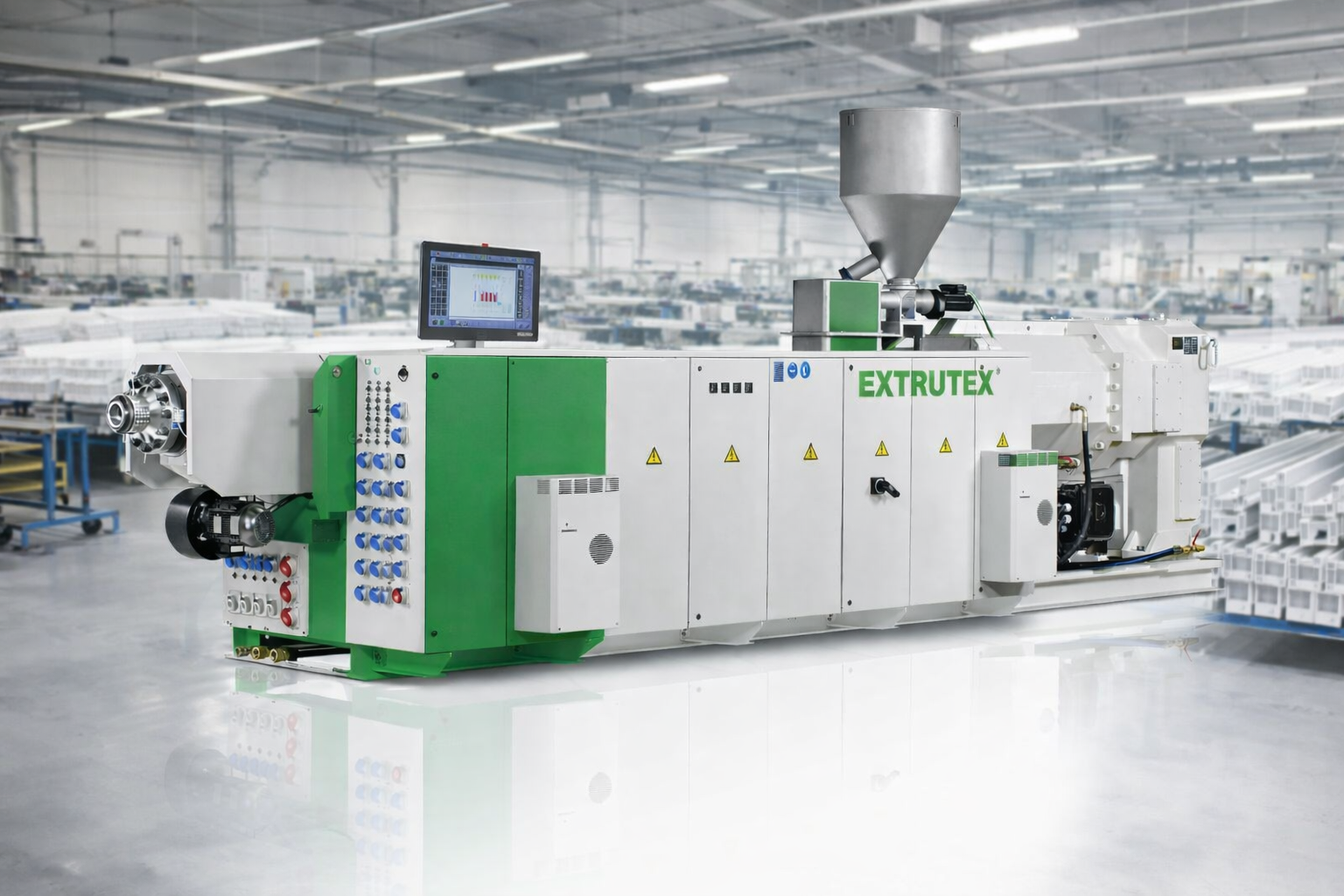
EXTRUTEX Optical Fiber Communication Microduct Bundle Pipe Extrusion Line
1. Product Overview
The EXTRUTEX Optical Fiber Communication Microduct Bundle Pipe Extrusion Line is designed for manufacturing small-diameter thermoplastic ducts and multi-duct bundles used in fiber-optic communication networks, telecommunications infrastructure, broadband expansion, and underground cable protection systems.
As fiber-optic networks continue to expand, communication infrastructure requires reliable, flexible, and well-organized pathways for installing and protecting optical cables. Microduct systems provide multiple individual channels within a compact arrangement, helping network operators organize cable routes and plan future network expansion.
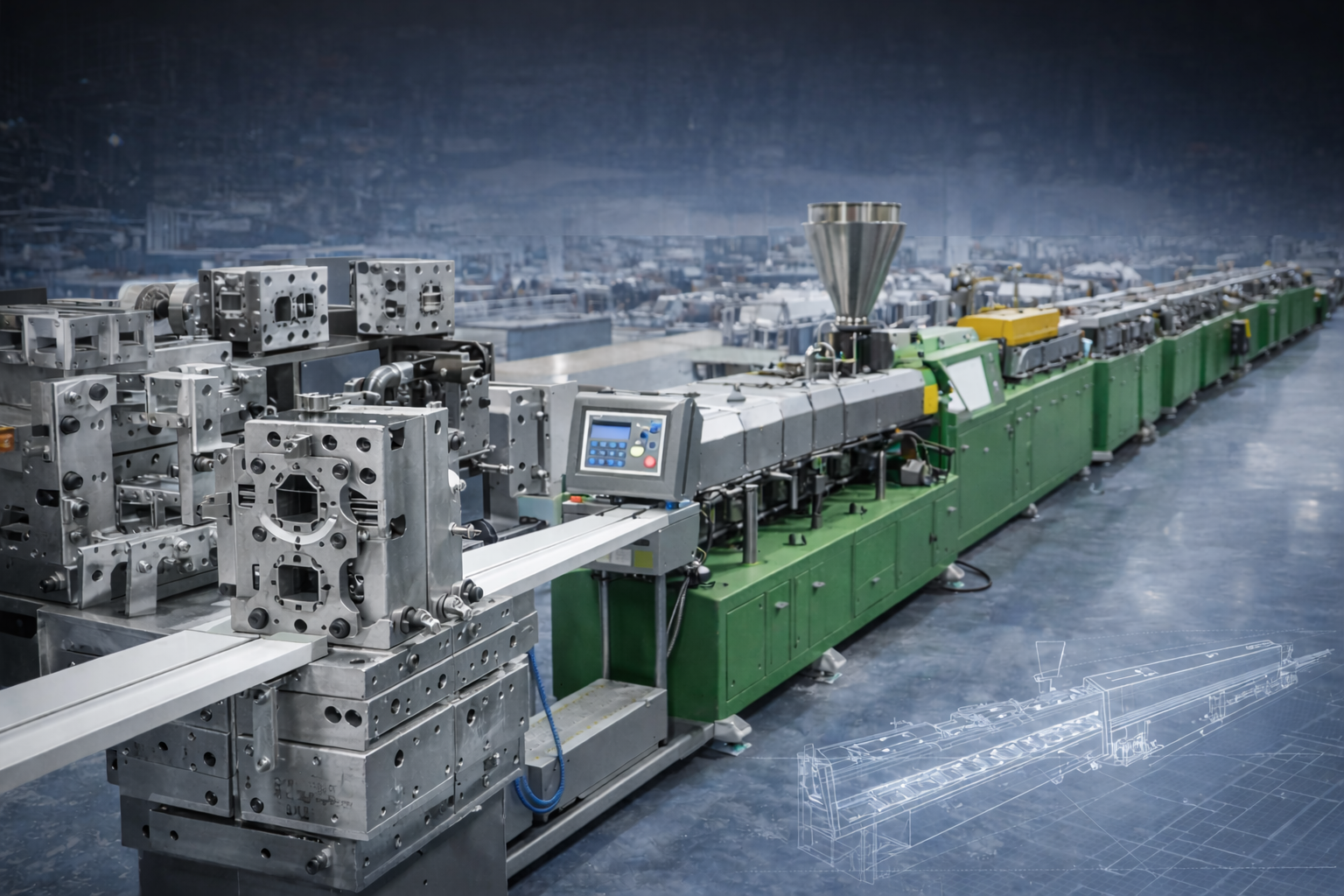
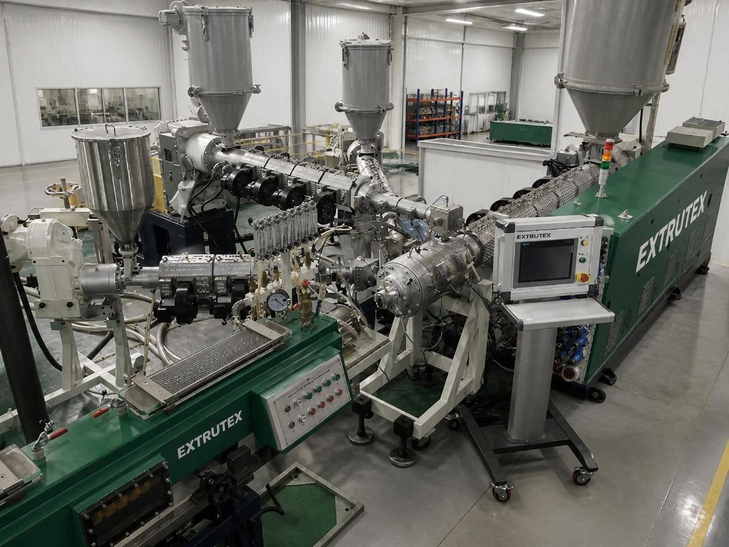
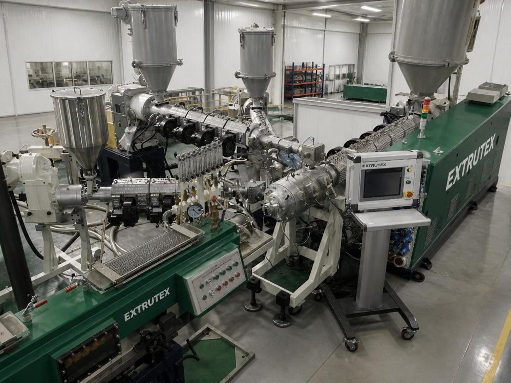
The EXTRUTEX production solution combines precision pipe extrusion, dimensional calibration, controlled cooling, haul-off, online inspection, microduct grouping, bundle assembly, and winding or cutting equipment. Depending on the required product, the line can be configured to manufacture individual microducts or integrate multiple ducts into a finished communication bundle.
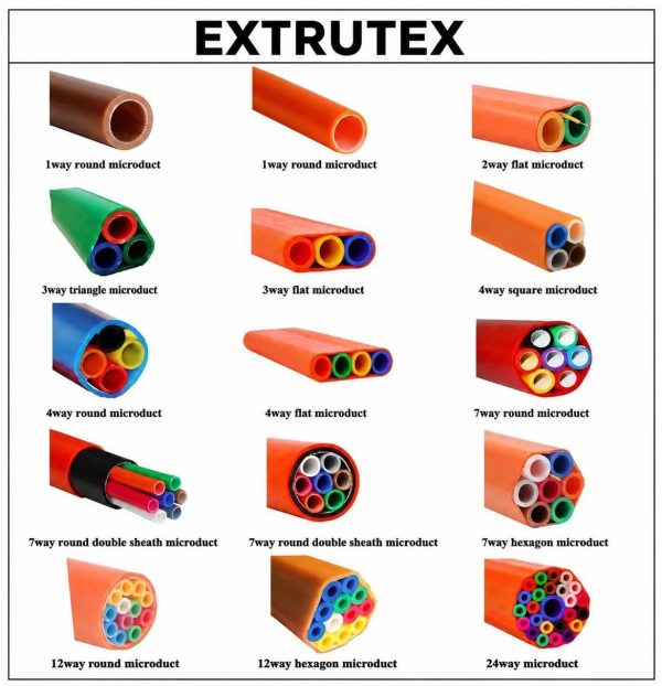
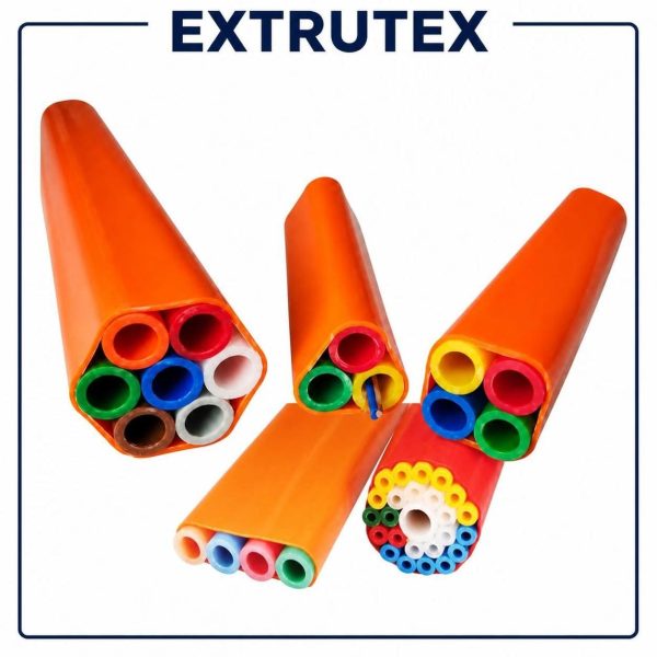
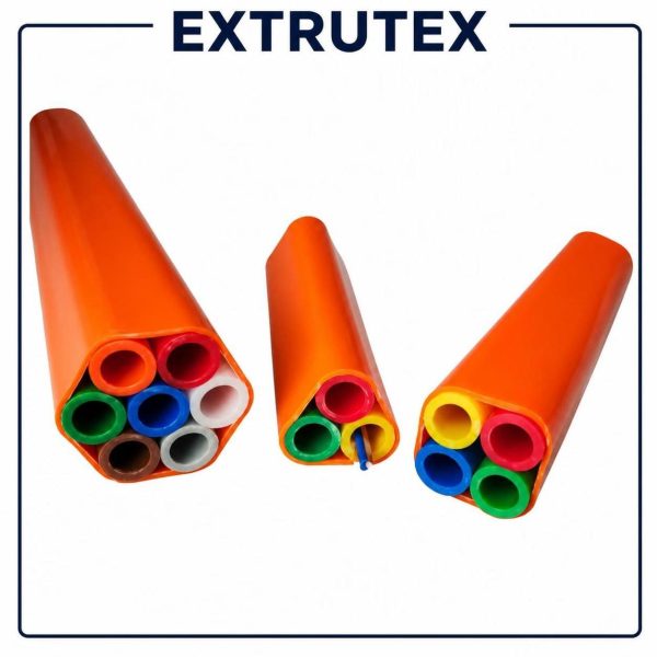
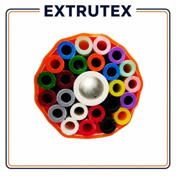
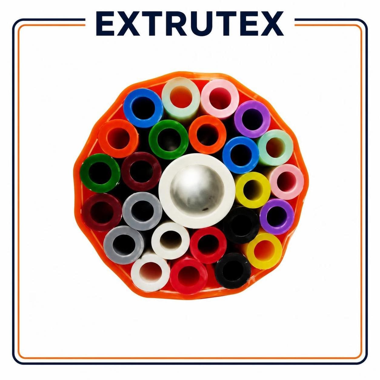
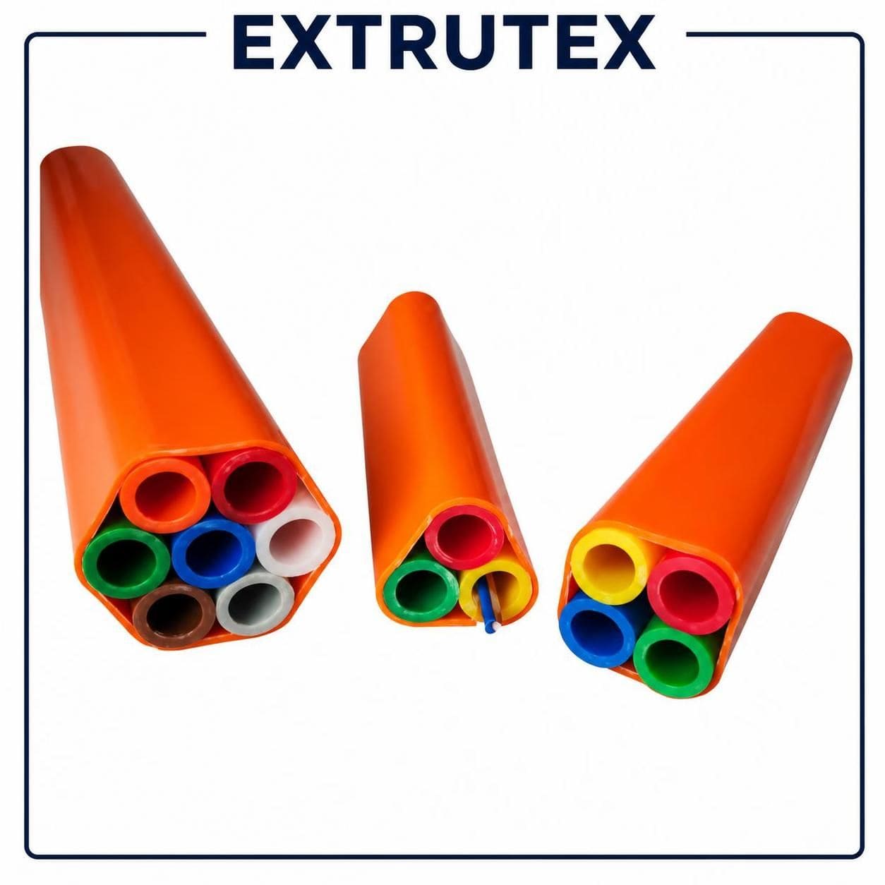
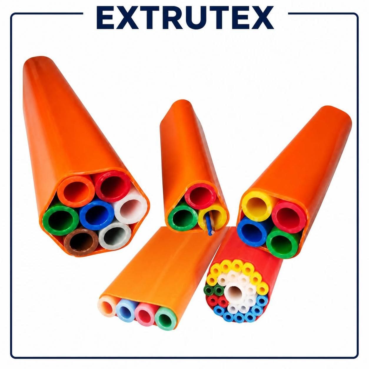
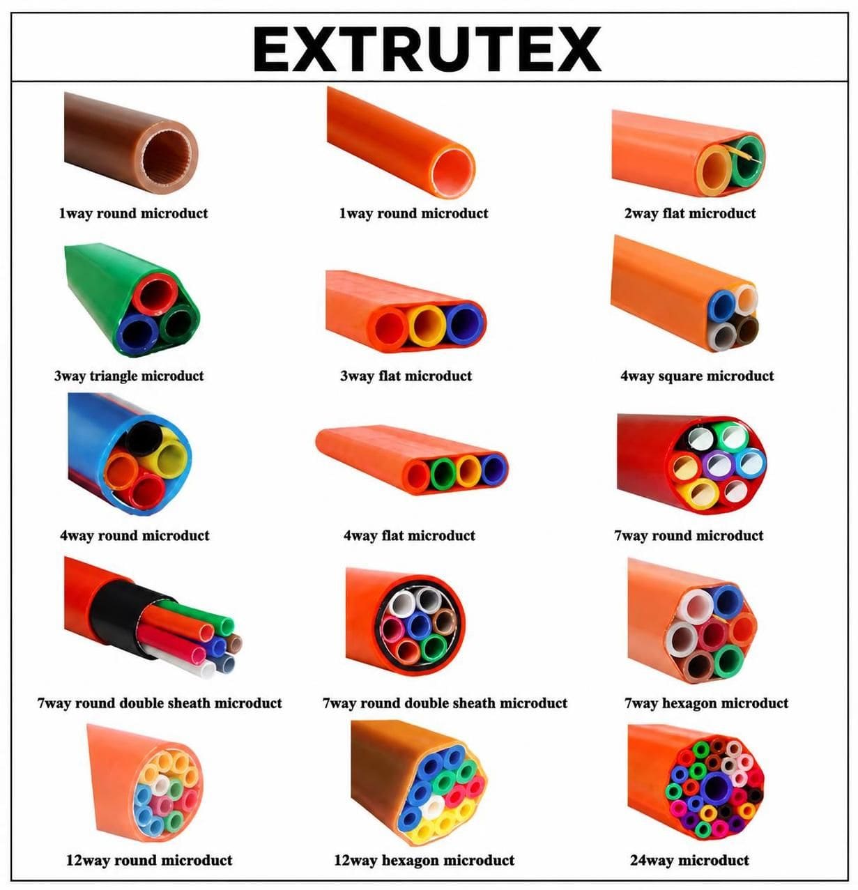
The production system can be engineered for microduct outside diameters of approximately 5–16 mm, with bundle arrangements including 1, 3, 4, 5, 6, 7, 12, 14, 19, and 24 ducts, as well as other customized configurations. Final dimensions, wall thicknesses, tolerances, and bundle geometry are determined by the selected product design and tooling.
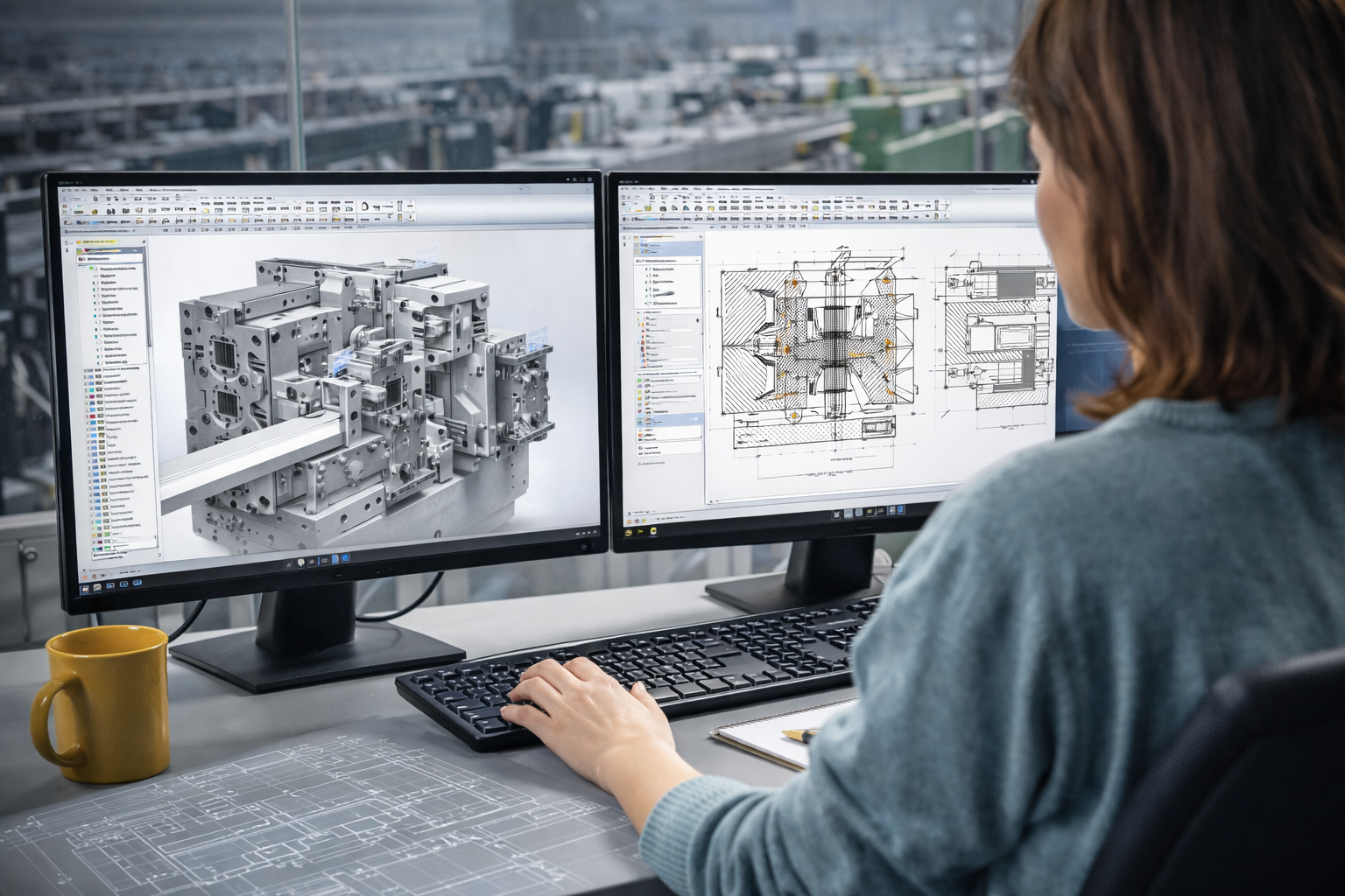
EXTRUTEX develops customized extrusion solutions according to the target polymer, pipe structure, production capacity, installation requirements, and factory conditions. The line can incorporate industrial automation and electrical components from recognized manufacturers, with Siemens and ABB options available for appropriate control and drive functions according to the final bill of materials.
**EXTRUTEX — Austrian design, with manufacturing in China and design, laboratory, and R&D capabilities in Austria.**
2. Main Advantages of the EXTRUTEX Microduct Bundle Pipe Line
- Customized microduct production: Designed for manufacturing small-diameter ducts in different outside diameters and wall thicknesses.
- Multiple bundle arrangements: Supports product planning for different duct counts and geometries.
- Stable dimensional control: Calibration, cooling, haul-off, and inspection systems help maintain consistent pipe dimensions.
- Flexible line configuration: Extruders, dies, calibration systems, and downstream units can be selected according to the required output.
- Continuous extrusion: Supports continuous production of thermoplastic microducts, with winding or cutting options for finished products.
- Integrated bundle assembly: Individual ducts can be organized and assembled using tooling designed for the specified bundle structure.
- Automation options: PLC control, touchscreen operation, drive control, temperature regulation, and selected online measurement systems can be incorporated.
- Industrial electrical components: Siemens and ABB components can be specified for compatible automation and drive applications.
- Application-specific engineering: The equipment layout can be developed according to the target material, product geometry, production speed, and installation market.
3. Applications
Telecommunications Networks
Microduct bundles provide organized pathways for optical fiber cables in telecommunications networks. Multiple ducts allow separate cable routes to be maintained within a compact system.
Fiber-to-the-Home Networks
Suitable microduct products can be used in fiber-to-the-home infrastructure, connecting distribution points, street cabinets, buildings, and subscriber locations. The specific duct design must be matched to the network installation method.
Underground Communication Infrastructure
Microduct bundles can be incorporated into underground telecommunications networks, road infrastructure projects, residential developments, industrial parks, and commercial campuses. The required pipe strength and construction depend on installation depth, external loads, soil conditions, and applicable standards.
Industrial and Campus Networks
Duct systems can support fiber-optic routing across factories, business parks, institutional campuses, and other facilities that require organized communication infrastructure.
Future Network Expansion
Where the network design allows, unused ducts can provide pathways for additional optical cables in the future. This can help reduce disruption when upgrading or extending an existing communication network.
4. Complete EXTRUTEX Production Line Equipment List
The following is a proposed equipment structure for a complete microduct bundle manufacturing system. Not every project requires every machine. The final configuration depends on whether the customer wants to produce individual microducts, assemble multiple ducts into bundles, or manufacture both products.
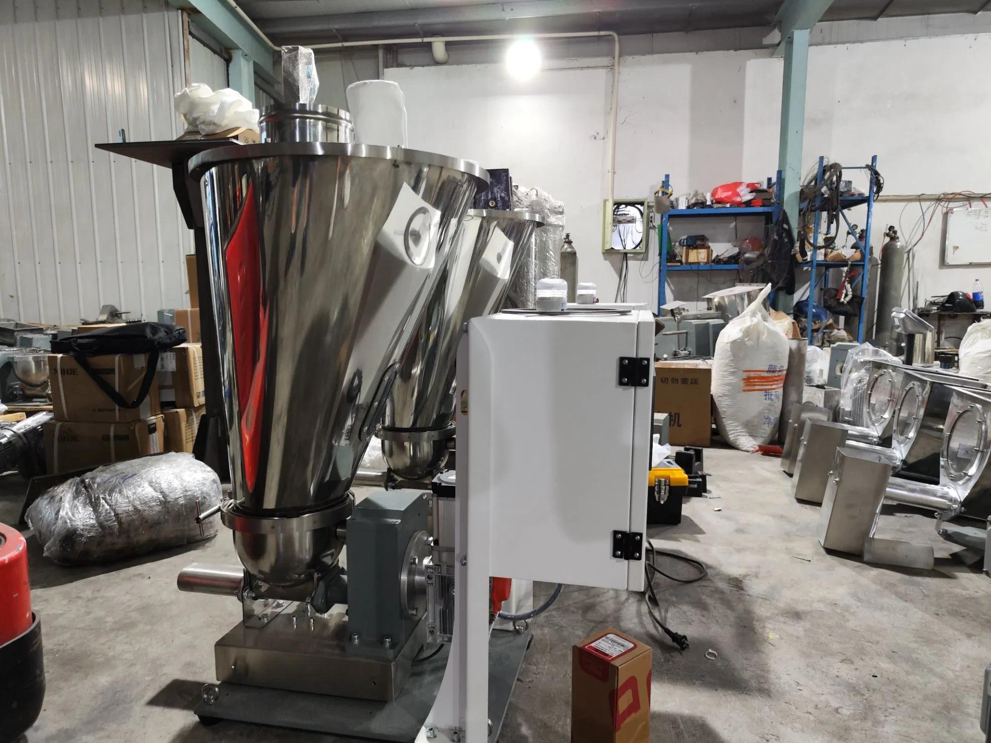
EX-01: Automatic Raw Material Loading System
The EX-01 Automatic Raw Material Loading System transfers plastic resin from storage containers or material bags to the extruder hopper. Depending on the factory layout, the system can use vacuum conveying, a central material conveying arrangement, or a dedicated hopper loader.
Its purpose is to reduce manual material handling and maintain a consistent supply of resin to the extrusion process. Material-contact components should be suitable for the selected polymer and the required production environment.
EX-02: Material Storage Hopper and Feeding Unit
The EX-02 Material Storage Hopper and Feeding Unit provides temporary storage and controlled feeding of the selected thermoplastic resin. Hopper capacity and feeding method are selected according to the extruder output and the customer's material-handling requirements.
A suitable feeding system helps reduce interruptions caused by inconsistent material supply. Where different materials or formulations are used, the system should also support appropriate material identification and cleaning procedures.
EX-03: Raw Material Mixing Unit
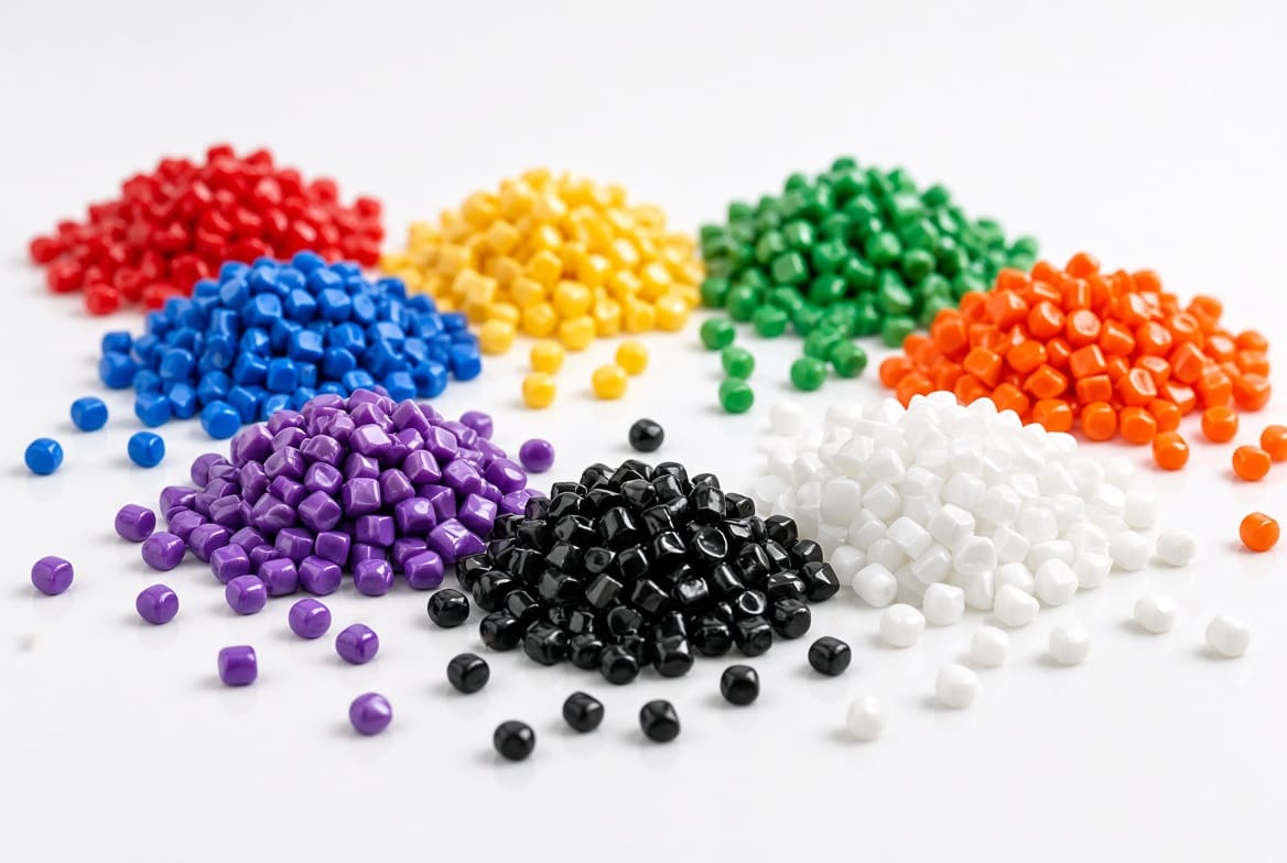
The EX-03 Raw Material Mixing Unit can be included when the product formulation requires controlled mixing of base resin with approved colorants, masterbatch, or compatible additives.
Mixing requirements depend on the resin supplier's recommendations and the final product specification. The mixing unit is optional where the customer uses ready-to-process material that does not require additional blending.
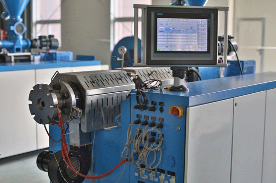
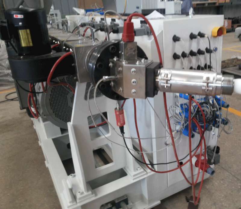
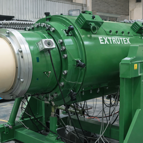
EX-04: Microduct Single-Screw Extruder
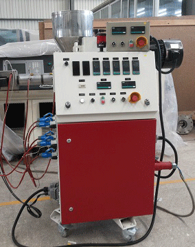
The EX-04 Microduct Single-Screw Extruder melts, conveys, and homogenizes the selected polymer before delivering the melt to the extrusion die.
The extruder is selected according to the required microduct diameter, wall thickness, resin grade, output, and operating speed. Screw diameter, screw geometry, L/D ratio, motor power, heating capacity, and temperature zones must be established during technical design.
For selected small-pipe applications, a screw diameter in the approximate 45–65 mm range may be considered during preliminary planning. This is an engineering starting point rather than a fixed specification for every configuration.
EX-05: Extruder Temperature Control System
The EX-05 Extruder Temperature Control System regulates the heating zones along the barrel and die. It may include temperature sensors, industrial controllers, heating elements, electrical protection, and control interfaces.
Stable temperature regulation helps maintain consistent polymer melting and melt delivery. The number of heating zones and the required temperature range depend on the extruder design and selected resin.
EX-06: Melt Pressure and Temperature Monitoring Unit
The EX-06 Melt Monitoring Unit can measure melt pressure and temperature at selected locations in the extrusion system. These readings help operators monitor process stability and identify abnormal operating conditions.
Sensor selection, pressure range, alarm limits, and data display are specified according to the final machine configuration.
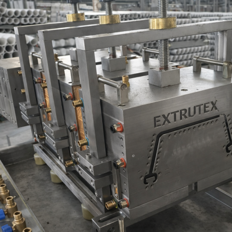
EX-07: Precision Microduct Extrusion Die
The EX-07 Precision Microduct Extrusion Die shapes the molten polymer into the required pipe geometry. The die is designed around the target outside diameter, wall thickness, material characteristics, and production rate.
Different pipe sizes or product constructions may require different die tooling. Proper die design and maintenance help support stable melt flow, uniform wall thickness, and a consistent pipe surface.
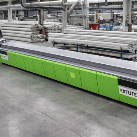
EX-08: Vacuum Calibration Tank
The EX-08 Vacuum Calibration Tank supports dimensional calibration of the extruded microduct. Depending on the pipe size and product design, a vacuum-assisted calibration system may be used to help maintain the required outside diameter and roundness during cooling.
Calibration components must be matched to the product dimensions. The vacuum level, water flow, and operating settings should be established through product trials.
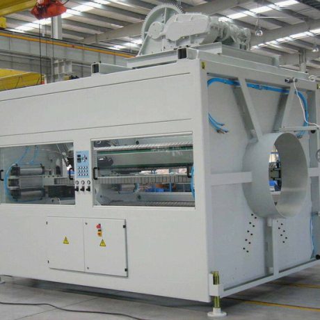
EX-09: Water Cooling Tank
The EX-09 Water Cooling Tank removes heat from the extruded pipe after shaping. Adequate cooling helps stabilize the pipe dimensions before haul-off and downstream processing.
Tank length, cooling capacity, water circulation, and temperature control depend on the material, wall thickness, line speed, and production requirements. Additional cooling sections may be necessary for some high-output configurations.
EX-10: Industrial Water Circulation and Cooling System
The EX-10 Industrial Water Circulation and Cooling System supplies and circulates cooling water to the calibration tank, cooling tank, and other equipment requiring water cooling.
The system may include circulation pumps, filtration, piping, temperature monitoring, and a suitable heat-rejection arrangement. The final cooling capacity must be calculated from the line's heat load and operating conditions.
EX-11: Servo-Controlled Haul-Off Unit
The EX-11 Servo-Controlled Haul-Off Unit pulls the calibrated microduct through the production line at a controlled speed. A stable haul-off system helps synchronize pipe movement with extruder output and supports dimensional consistency.
The number and design of belts or pulling tracks depend on the pipe diameter and the required traction. Pulling force should be sufficient to transport the product without crushing or deforming the duct.
EX-12: Online Diameter Measurement System
The EX-12 Online Diameter Measurement System can monitor the outside diameter of the microduct during production. Depending on the selected instrument, measurements can be displayed to the operator and used for process monitoring.
Online measurement can help identify deviations early and reduce the quantity of out-of-specification product. Measurement range, accuracy, and installation position must be selected for the required pipe dimensions.
EX-13: Wall Thickness and Product Inspection Equipment
The EX-13 Inspection Equipment supports quality checks on wall thickness and other critical product characteristics. The appropriate solution may use offline sampling, specialized gauges, or compatible online measurement technology.
The required inspection method depends on the wall thickness, tolerances, material, and applicable customer or industry standards. Online wall-thickness measurement should only be included where the selected equipment supports the required dimensions and accuracy.
EX-14: Microduct Surface Marking and Printing Unit
The EX-14 Surface Marking and Printing Unit can print product identification, length markings, production codes, or other agreed information on the microduct surface.
Printing method, ink compatibility, marking speed, and printing content depend on the material and customer requirements. Marking must not compromise the pipe's intended performance.
EX-15: Microduct Accumulation and Transfer Unit
The EX-15 Accumulation and Transfer Unit provides a controlled transition between continuous extrusion and downstream cutting, winding, or bundle assembly. It can help coordinate different operating speeds and reduce unnecessary interruptions where the selected production arrangement requires accumulation.
The appropriate design depends on the duct's flexibility, minimum bending radius, line speed, and factory layout.
EX-16: Automatic Microduct Cutting Machine
The EX-16 Automatic Microduct Cutting Machine cuts individual ducts to specified lengths. It may use a length-measuring system, synchronized cutting mechanism, and programmable control.
Cutting accuracy, maximum diameter, available length range, and operating speed must be confirmed for the intended product. The cutting unit may be optional where the finished product is supplied in continuous coils.
EX-17: Microduct Coiling and Winding Machine
The EX-17 Microduct Coiling and Winding Machine winds finished microducts into coils or onto reels. Winding tension and coil dimensions should be controlled to prevent excessive deformation and maintain the product's required bending characteristics.
The winding system can be selected according to the pipe diameter, duct flexibility, required coil length, and transport method.
EX-18: Individual Microduct Collection and Storage System
The EX-18 Collection and Storage System provides organized handling of individual ducts before they are assembled into a bundle. It can include reels, coil stands, transfer supports, or other suitable handling components.
A well-planned collection arrangement helps reduce tangling, surface damage, and unnecessary handling during bundle assembly.
EX-19: Multi-Microduct Arrangement and Assembly Unit
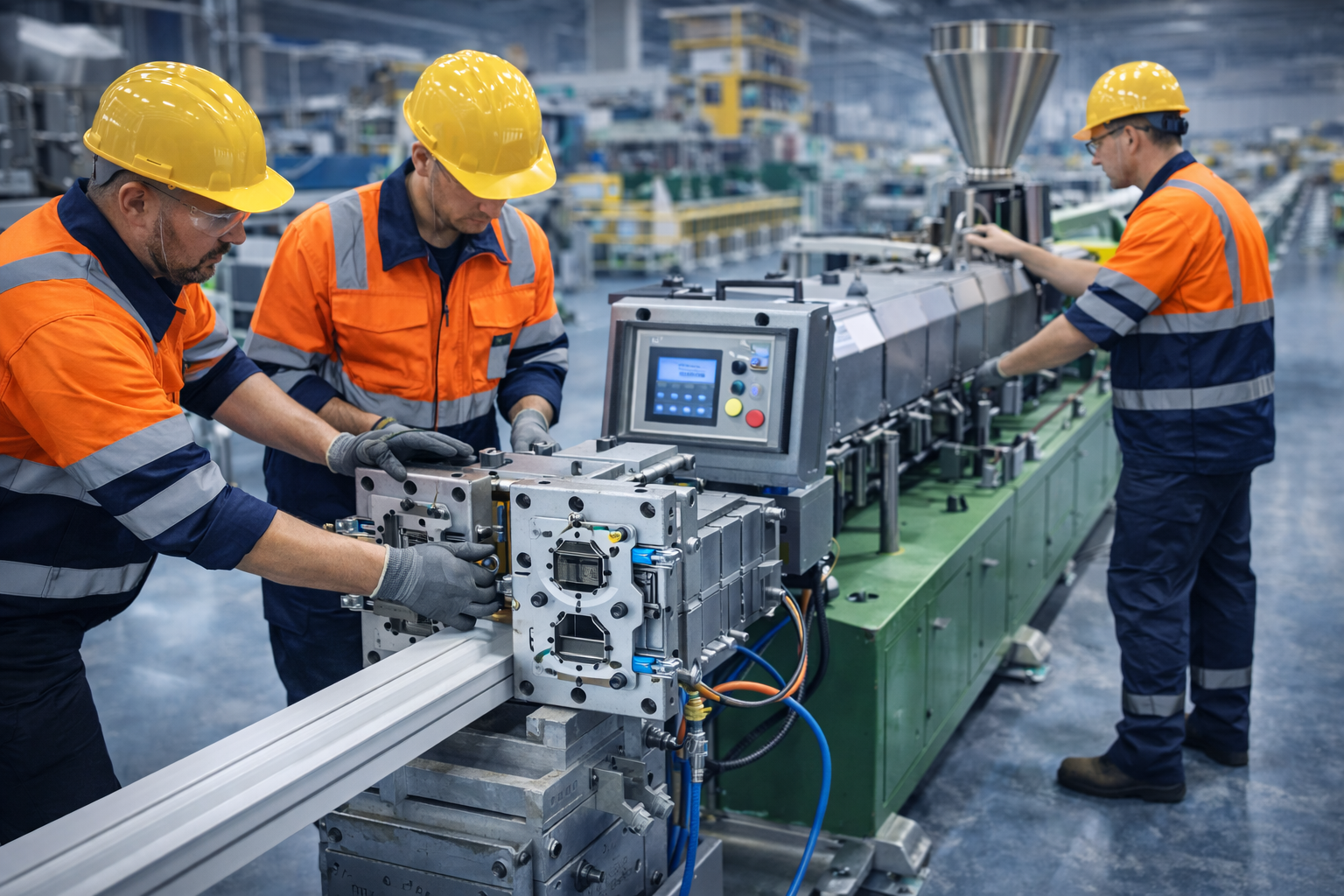
The EX-19 Multi-Microduct Arrangement and Assembly Unit organizes individual microducts into the specified bundle configuration. Guides and assembly tooling maintain the intended duct positions as the bundle is formed.
Tooling must be developed for the required duct count, layout, bundle dimensions, and any additional joining or retaining method specified by the customer.
EX-20: Bundle Forming and Consolidation Unit
The EX-20 Bundle Forming and Consolidation Unit supports the formation of a stable multi-duct bundle. Depending on the product design, the system may guide, align, wrap, or otherwise consolidate the ducts into the required finished arrangement.
The final construction must prevent unacceptable duct deformation and remain suitable for storage, transport, and installation. The required assembly method should be confirmed from the product drawing.
EX-21: Bundle Outer Wrapping or Retaining Unit
The EX-21 Outer Wrapping or Retaining Unit can be incorporated when the finished bundle requires an outer wrap, retaining tape, or another specified method of maintaining the duct arrangement.
The choice of wrapping material and process depends on the intended application and the bundle design. This equipment is optional if the selected product does not require an additional retaining layer.
EX-22: Finished Bundle Haul-Off Unit
The EX-22 Finished Bundle Haul-Off Unit transports the assembled bundle through downstream operations at a controlled speed. It must accommodate the finished bundle's outside dimensions and avoid excessive compression.
Speed synchronization with the assembly and winding equipment is important for stable continuous production.
EX-23: Finished Bundle Cutting Machine
The EX-23 Finished Bundle Cutting Machine cuts assembled bundles to specified lengths where the product is supplied in straight sections rather than coils.
The cutting mechanism and support arrangement should be selected to maintain a clean cut without damaging individual microducts or deforming the bundle.
EX-24: Automatic Bundle Coiling or Reel Winding Machine
The EX-24 Automatic Bundle Coiling or Reel Winding Machine collects flexible bundles into coils or onto reels. Its design must account for bundle diameter, flexibility, minimum bending radius, and required finished length.
Large or relatively stiff bundles may require a different handling method from small, flexible bundles. The selected winding equipment should therefore be confirmed against the final product dimensions.
EX-25: Central PLC Control and HMI System
The EX-25 Central PLC Control and HMI System coordinates the main production operations. Depending on the final scope, it can monitor extrusion temperatures, drive speeds, alarms, line status, and selected downstream functions.
A touchscreen interface can provide operating screens, parameter entry, alarm messages, and diagnostic information. The extent of integration depends on whether the customer selects an individual microduct line, a complete bundle line, or multiple synchronized extrusion units.
EX-26: Electrical Cabinet and Drive Control System
The EX-26 Electrical Cabinet and Drive Control System houses the electrical equipment required to power and control the production line. It can include circuit protection, motor-control equipment, variable-frequency drives, control power supplies, terminals, and other components appropriate to the final design.
Siemens and ABB components can be specified for compatible PLC, drive, or motor-control functions. Exact brands and models must be listed in the final electrical documentation rather than assumed for every component.
EX-27: Finished Product Inspection and Testing Station
The EX-27 Finished Product Inspection and Testing Station supports final quality checks before the product is packed or dispatched. Tests may include dimensional verification, visual inspection, wall-thickness sampling, mechanical checks, and other evaluations defined by the product specification.
The testing equipment should be selected according to the intended application and applicable standards. Specialized laboratory tests may require separate instruments and procedures.
EX-28: Finished Product Handling and Packing Station
The EX-28 Finished Product Handling and Packing Station supports organized packing of microduct coils, reels, or cut bundles. The arrangement can include protective wrapping, identification labels, length or batch information, and preparation for storage or transport.
Packaging should protect the ducts from contamination, deformation, and handling damage during shipment and installation.
5. Preliminary Technical Specifications
The following values are preliminary engineering references for planning a microduct extrusion and bundle assembly project. They are not guaranteed specifications for a particular EXTRUTEX model. Final values must be confirmed after the customer supplies the product drawings and production requirements.
| Parameter |
Preliminary Engineering Reference |
| Product |
Optical fiber communication microducts and multi-duct bundles |
| Applicable material |
HDPE or other suitable thermoplastics, subject to product design |
| Individual microduct outside diameter |
Approximately 5–16 mm |
| Bundle duct count |
1, 3, 4, 5, 6, 7, 12, 14, 19, 24, or customized |
| Proposed extruder screw diameter |
Approximately 45–65 mm for selected small-pipe configurations |
| Proposed screw L/D ratio |
Approximately 28:1–36:1, subject to extruder design |
| Estimated individual microduct line speed |
Approximately 10–60 m/min, depending on pipe dimensions and process conditions |
| Estimated assembled bundle speed |
Approximately 5–30 m/min, depending on duct count and assembly method |
| Preliminary output per extrusion unit |
Approximately 30–120 kg/h for selected configurations; to be verified |
| Calibration |
Product-specific sizing and calibration system |
| Cooling |
Water cooling, with capacity selected according to output and line speed |
| Haul-off |
Variable-speed or servo-controlled system, subject to configuration |
| Cutting and winding |
Selected according to product length, flexibility, and packaging method |
| Automation |
PLC and HMI options |
| Electrical brands |
Siemens and ABB options for appropriate components, subject to final bill of materials |
| Installed power and line dimensions |
To be confirmed after equipment selection and layout design |
Technical note: Output and speed depend on pipe diameter, wall thickness, resin properties, number of extrusion units, die design, cooling capacity, and bundle assembly requirements. The preliminary ranges above should not be presented as guaranteed production performance until verified by the final technical proposal and production trials.
6. Microduct Production Speed and Capacity
Production speed is determined by the combination of polymer throughput, product dimensions, cooling capacity, and dimensional tolerances. Small-diameter microducts with thinner walls may permit higher line speeds than products with larger diameters or thicker walls.
For initial planning, individual microduct extrusion may be evaluated within an approximate range of 10–60 m/min. Finished bundle assembly may operate at a different speed, with an approximate planning range of 5–30 m/min. These ranges are indicative only and must be validated for the selected configuration.
A bundle containing many microducts may require several synchronized extrusion units or a separate assembly process. The number of ducts in the final bundle does not by itself determine the number of extruders: this depends on whether the ducts are produced simultaneously, produced separately and assembled later, or manufactured using another approved production arrangement.
When calculating production capacity, EXTRUTEX should evaluate the required pipe dimensions, polymer consumption, target speed, product length, and expected operating schedule. A high linear speed is useful only when the line can maintain the specified product quality and stable continuous operation.
7. Quality Control and Dimensional Stability
Consistent microduct production requires coordinated control of extrusion, calibration, cooling, and haul-off. Important quality checks may include:
- Outside diameter and dimensional tolerance.
- Wall thickness and wall-thickness uniformity.
- Ovality and pipe deformation.
- Surface appearance and visible defects.
- Bundle outside dimensions and duct arrangement.
- Mechanical properties required for the installation environment.
- Compatibility with the intended optical fiber installation method.
- Product identification, batch traceability, and finished length.
The test methods and acceptance limits should be defined according to the customer's product specification and applicable market standards. Where required, dedicated laboratory instruments can be supplied or integrated into the quality-control workflow.
8. Automation and Electrical Configuration
The EXTRUTEX production line can use a centralized PLC and HMI arrangement to coordinate selected extrusion and downstream functions. The degree of integration depends on the production-line scope and the number of machines included.
Electrical and automation options can include:
- PLC-based machine control.
- Industrial touchscreen operation.
- Extruder barrel and die temperature regulation.
- Variable-speed or servo drive control.
- Motor protection and electrical safety circuits.
- Alarm indication and process-status monitoring.
- Selected diameter or production-speed measurement interfaces.
- Emergency-stop functions and appropriate machine guarding.
Siemens and ABB components can be selected for suitable PLC, drive, and electrical control functions. The final component list should identify the manufacturer and model for each agreed item. Electrical design, guarding, and safety functions must be reviewed against the destination country's requirements.
9. Installation, Commissioning, and Maintenance
Before installation, the factory should prepare suitable space for the extruder, die, calibration system, cooling tanks, haul-off, assembly equipment, winding or cutting units, and operator access.
Utilities such as electrical power, cooling water, compressed air where required, ventilation, and material-handling provisions should be checked against the final machine layout. The foundation and floor arrangement should support the equipment and allow safe maintenance access.
Commissioning should include checking the electrical connections, heating zones, drive rotation, cooling-water flow, sensor readings, safety devices, and control functions. Initial production trials should use the selected resin and target product specification.
Routine maintenance may include cleaning the die and material-contact components, checking heaters and sensors, inspecting drive systems, maintaining water filters and pumps, and verifying calibration and measurement equipment. Maintenance intervals should be established according to the machine manuals, operating conditions, and production schedule.
10. Frequently Asked Questions
What material can be used for communication microducts?
HDPE is a common option for communication microducts. The exact resin grade and material formulation should be selected according to the product design, installation environment, and applicable standards.
What microduct sizes can the line produce?
The proposed product range is approximately 5–16 mm outside diameter. Exact diameters, wall thicknesses, and tolerances depend on the tooling and final product specification.
Can the line manufacture 12-duct or 24-duct bundles?
The production solution can be engineered for these configurations. The extrusion arrangement, assembly tooling, and downstream equipment must be designed around the required bundle drawing and production target.
What production speed can be expected?
Preliminary planning ranges are approximately 10–60 m/min for individual microduct extrusion and 5–30 m/min for assembled bundles. Actual speeds must be confirmed for the selected dimensions, resin, and equipment configuration.
Can Siemens and ABB electrical components be included?
Yes. Siemens and ABB options can be specified for compatible automation and drive functions. Exact component models and quantities should be confirmed in the final technical documentation.
Can the equipment produce both individual microducts and assembled bundles?
Yes, subject to the selected line scope. Individual microduct production and bundle assembly may be integrated into one system or arranged as separate production stages.
What information is needed for a technical quotation?
The most useful information includes the required microduct diameters, wall thicknesses, number of ducts per bundle, bundle geometry, resin grade, target speed, coil or cut length, and destination-country electrical requirements.
11. Request a Customized EXTRUTEX Microduct Production Line
EXTRUTEX can develop an optical fiber communication microduct bundle pipe production solution based on your product drawings, required dimensions, bundle arrangement, target output, and factory conditions.
When making an inquiry, please specify:
- Individual microduct outside diameter and wall thickness.
- Required duct counts and bundle configuration.
- Applicable resin grade and any special material requirements.
- Target line speed and daily production quantity.
- Required finished length, coil diameter, or reel format.
- Whether microduct extrusion and bundle assembly should be integrated.
- Preferred electrical and automation component brands.
- Destination-country power supply and relevant product standards.
Based on these requirements, EXTRUTEX can assess the extruder configuration, precision dies, calibration and cooling equipment, haul-off, online inspection, bundle assembly, cutting or winding system, and electrical control package needed for your project.
EXTRUTEX — Austrian design, with manufacturing in China and design, laboratory, and R&D capabilities in Austria.








-
(0 customer reviews)