No products in the cart.

All rights of this website are reserved for EXTRUTEX Austria and its partner companies, © 2026
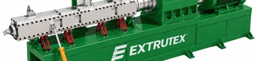
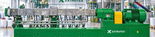
EXTRUTEX Twin Screw co-rotating Extruder Screw Shafts

Multiple Payment Methods

Discount for advance payments over 50%

Free Shipping Coordination Services
Payment methods:

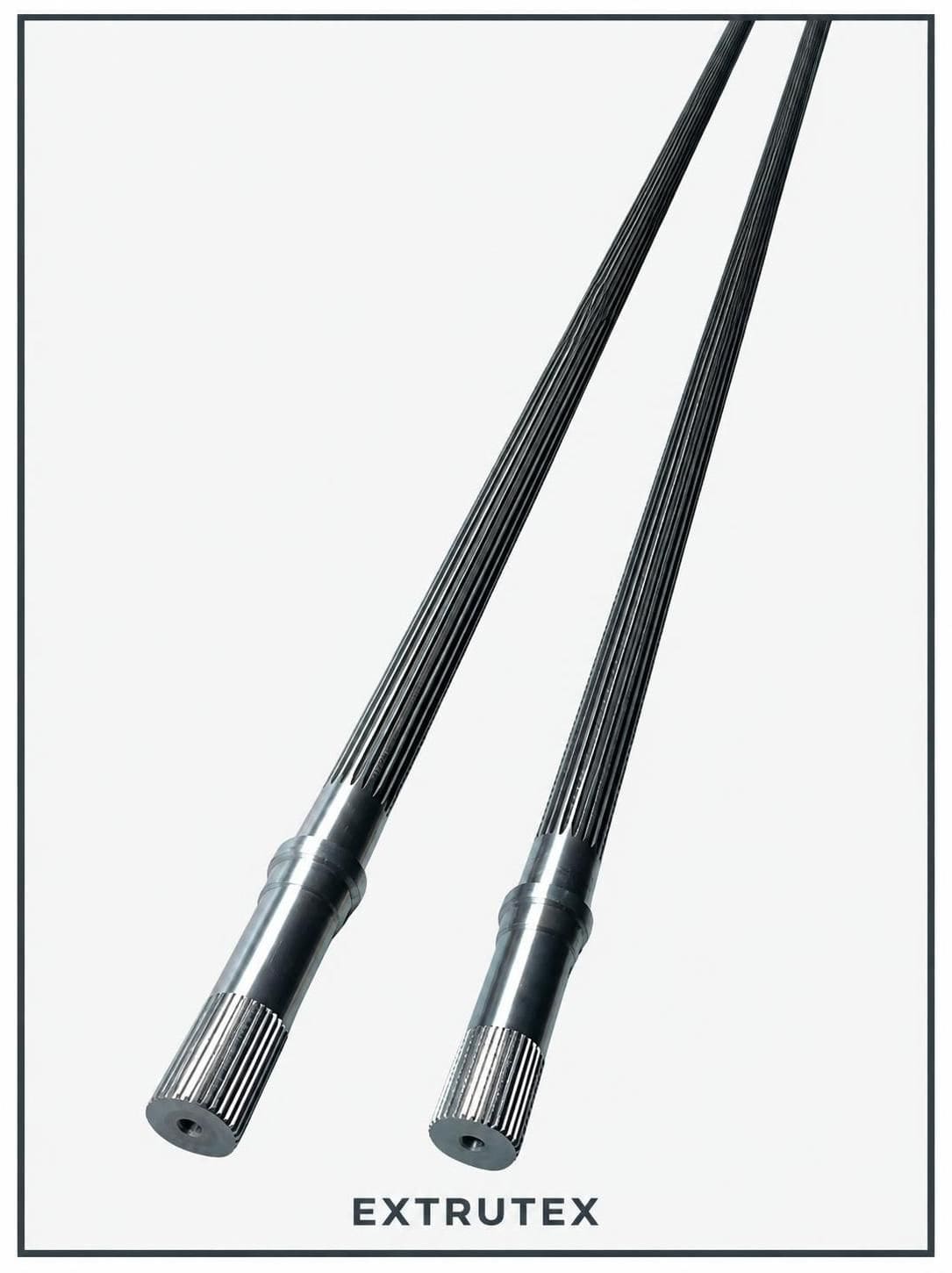
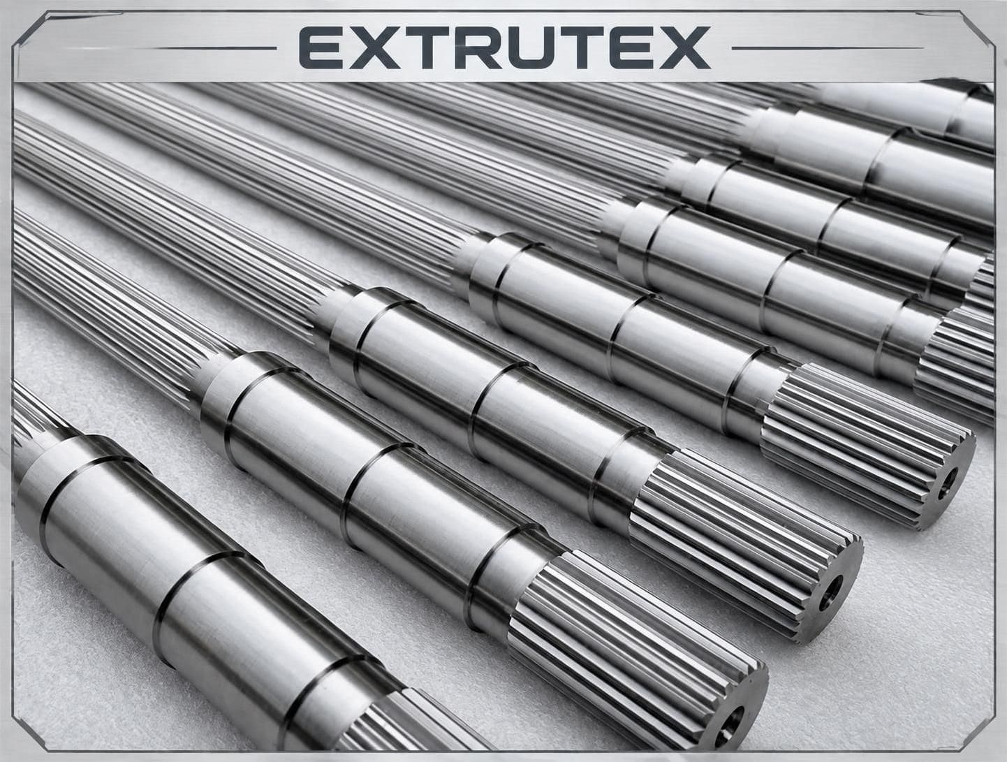
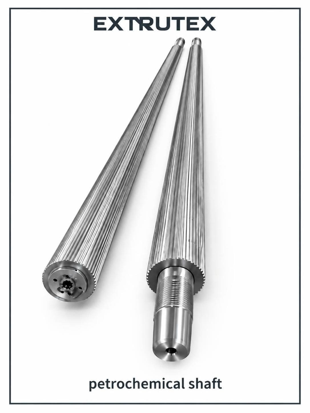
EXTRUTEX Twin Screw Extruder Screw Shafts are precision-engineered drive components designed for co-rotating and counter-rotating twin screw extrusion systems. The screw shaft provides the mechanical connection between the gearbox and the screw elements, transmitting torque while maintaining the alignment and stability required for continuous extrusion operation.
Manufactured according to technical drawings, equipment specifications and application requirements, EXTRUTEX screw shafts can be supplied for replacement, maintenance, refurbishment and new extruder projects. Material selection, spline geometry, heat treatment, machining accuracy and shaft configuration are considered according to the operating conditions of the equipment.
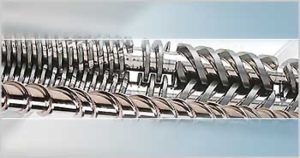
A twin screw extruder uses two rotating screw assemblies to convey, melt, mix, compound and homogenize polymer materials. Each screw assembly consists of a shaft and a series of interchangeable screw elements, such as conveying elements, kneading blocks, mixing elements and other functional components.
The screw shaft is the central mechanical component supporting these elements. It transmits rotational power from the gearbox and transfers torque to the screw configuration. Its geometry and mechanical properties have a direct influence on the reliability of the extrusion system.
Unlike a simple solid shaft, a twin screw extruder shaft must accommodate the specific coupling and mounting requirements of the screw elements. Its spline profile, shaft diameter, length, surface treatment and connection arrangement must therefore match the original equipment design.
EXTRUTEX screw shafts are manufactured according to the dimensions and technical requirements of the target extruder. The following table summarizes the main specification categories available for engineering and manufacturing discussions.
| Parameter | Specification |
|---|---|
| Product | Twin screw extruder screw shaft |
| Spline type | Involute spline |
| Spline standard | DIN 5480 or according to original equipment drawings |
| Available materials | 40CrNiMo, H13, WR15E and other specified materials |
| Heat treatment | Nitriding or induction hardening, according to design requirements |
| Diameter range | 7–486 mm, subject to design and manufacturing requirements |
| Length | Manufactured according to OEM drawings or customer specifications |
| Configuration | Single-piece or coupled shaft arrangements |
| Runout | Full-length runout controlled according to the specified drawing tolerance |
| Drive protection | Torque-limiting coupling or shear-pin arrangement, where specified |
| Supply | Stock availability and custom manufacturing according to specification |
| Typical imported-machine lead time | Approximately 30–45 days, subject to material and manufacturing requirements |
Material selection is an important part of screw shaft engineering. The shaft must provide suitable mechanical strength and resistance to the operating loads generated during extrusion. The correct material depends on shaft dimensions, gearbox output, torque requirements, equipment design and manufacturing conditions.
40CrNiMo is an alloy structural steel used for mechanical components requiring a combination of strength and toughness. It can be considered for screw shaft applications where the design requires a strong load-bearing core and suitable mechanical properties after heat treatment.
Material condition and heat treatment should be selected according to the shaft drawing and intended service conditions.
H13 is a chromium-molybdenum-vanadium hot-work tool steel. It is used in demanding industrial applications where appropriate hardness, toughness and thermal performance are required. Its suitability for a specific screw shaft depends on the design and the required mechanical properties.
WR15E is a material designation included in the available shaft material specifications. The exact chemical composition, material standard and heat-treatment requirements should be confirmed against the relevant material documentation before production.
| Material | Material category | Engineering considerations |
|---|---|---|
| 40CrNiMo | Alloy structural steel | Strength, toughness and suitability for mechanical shaft applications |
| H13 | Hot-work tool steel | Hardness, toughness and thermal performance according to heat treatment |
| WR15E | Specified shaft material designation | Requires confirmation of material documentation and design requirements |
Heat treatment is used to achieve the mechanical properties required by the shaft design. Depending on the selected material and application, EXTRUTEX screw shafts can be specified with nitriding or induction hardening.
Nitriding is a surface-hardening process that introduces nitrogen into the surface layer of suitable steels. It is used to improve surface hardness and wear resistance while maintaining the properties of the underlying material.
For screw shafts, nitriding requirements should consider the spline geometry, shaft dimensions, material composition and dimensional tolerances. The process must be controlled to avoid unacceptable distortion or dimensional changes.
Induction hardening uses electromagnetic induction to heat selected areas of a steel component, followed by controlled cooling. It can be used where localized surface hardening is required.
The appropriate hardening depth and hardness specification depend on the shaft design and the areas exposed to mechanical contact or wear.
| Process | Purpose | Important considerations |
|---|---|---|
| Nitriding | Improve surface hardness and wear resistance | Material compatibility, case depth and dimensional control |
| Induction hardening | Harden selected surface areas | Hardening depth, treatment location and distortion control |
The spline connection is one of the most important features of a twin screw extruder shaft. It provides the mechanical interface between the shaft and the screw elements, allowing torque to be transferred through the assembled screw configuration.
EXTRUTEX screw shafts can be manufactured with involute spline profiles according to DIN 5480 or the original equipment manufacturer's drawing. The final spline dimensions must be confirmed before manufacturing.
DIN 5480 is a standard used for involute splined connections. When this standard is specified, the relevant profile and dimensional details must be confirmed for the specific shaft design.
| Parameter | Required information |
|---|---|
| Spline standard | DIN 5480 or another specified standard |
| Module | According to drawing |
| Number of teeth | According to drawing |
| Pressure angle | According to specified spline profile |
| Reference diameter | According to drawing |
| Fit and tolerance | According to the mating screw elements |
| Effective spline length | According to shaft configuration |
Even when two shafts have similar outside diameters, their spline profiles may differ. A replacement shaft should not be selected by outside diameter alone. The spline module, tooth count, profile, fit and effective engagement length must all be checked.
Twin screw extruder shafts can be designed in different configurations depending on the equipment architecture, overall shaft length, drive arrangement and manufacturing requirements.
A single-piece shaft is manufactured as one continuous component. Its dimensions and geometry are determined by the equipment design. Full-length straightness and runout are important inspection considerations, particularly for longer shafts.
Some equipment designs use coupled shaft arrangements. The coupling connects the relevant shaft sections or drive components according to the original mechanical design.
Coupled arrangements require accurate control of the connection geometry and alignment. The coupling method must be confirmed from the equipment drawing rather than assumed from the external appearance of the shaft.
| Configuration | Description | Key considerations |
|---|---|---|
| Single-piece shaft | One continuous shaft component | Overall length, straightness, runout and machining accuracy |
| Coupled shaft | Configuration incorporating a specified coupling connection | Connection geometry, alignment and torque transmission |
During operation, the screw shaft transfers torque from the gearbox to the screw elements. The actual loading depends on the extrusion process, screw configuration, material characteristics, operating speed and machine design.
In polymer compounding applications, the shaft may experience changing mechanical loads as materials move through conveying, melting, mixing and kneading sections. The mechanical design must therefore be suitable for the intended operating conditions.
Screw shafts operate under mechanical loads and repeated operating cycles. Over time, wear or damage may develop in the spline area, drive connection or shaft body. Proper inspection helps identify the condition of the shaft and determine whether repair or replacement is appropriate.
Torsional fatigue can develop when a shaft experiences repeated twisting loads. The risk depends on material properties, shaft geometry, operating torque and the number and severity of load cycles.
Fretting can occur at contacting surfaces exposed to small repeated relative movements. In a spline connection, inadequate fit, vibration or operating conditions may contribute to surface damage.
Spline tooth wear can reduce the quality of the mechanical connection between the shaft and mating components. Worn spline profiles may result in excessive clearance or improper engagement.
Journal surfaces may wear when their operating contact conditions are not maintained. Inspection should evaluate surface condition, dimensions and alignment against the relevant drawing.
Excessive runout or shaft deformation can affect assembly and operation. A shaft should be inspected along its full length, using suitable measurement equipment and the specified tolerance requirements.
Where a coupling is used, damage or wear in the connection area may affect torque transmission. The coupling and its mating components should be checked together during maintenance.
| Potential problem | Possible inspection focus | Recommended evaluation |
|---|---|---|
| Torsional fatigue | Cracks, deformation and material condition | Assess against loading history and engineering requirements |
| Fretting corrosion | Contact surfaces and spline engagement | Check fit, surface damage and alignment |
| Spline tooth wear | Tooth profile and clearance | Measure and compare with drawing requirements |
| Journal wear | Diameter and surface condition | Measure against original dimensions |
| Excessive runout | Full-length shaft geometry | Measure with suitable precision instruments |
| Coupling damage | Connection surfaces and mating components | Inspect the complete coupling arrangement |
Precision manufacturing is essential because the shaft must fit the gearbox connection and the screw elements correctly. Manufacturing requirements are determined by the approved drawing and technical specifications.
Before production, the shaft drawing should be reviewed to confirm overall dimensions, spline geometry, material, heat treatment, connection details and tolerances.
The selected steel material should match the approved specification. Material documentation and identification should be checked according to the agreed quality requirements.
Machining operations establish the shaft geometry and critical dimensions. The machining sequence depends on the design, material and required surface treatment.
The spline profile is manufactured according to the specified standard or drawing. Correct profile geometry and dimensional accuracy are important for the mating screw elements.
Where required, the shaft undergoes the specified nitriding or induction-hardening process. Treatment parameters should follow the approved material and engineering requirements.
After manufacturing and treatment, the shaft should be inspected against the approved drawing. Relevant checks may include dimensional measurements, spline inspection, surface condition and full-length runout.
| Quality control stage | Inspection focus |
|---|---|
| Drawing review | Dimensions, spline profile, tolerances and configuration |
| Material verification | Material designation and relevant documentation |
| Machining inspection | Critical dimensions and geometric accuracy |
| Spline inspection | Profile, tooth geometry and mating fit |
| Heat treatment inspection | Specified process and required treatment condition |
| Final inspection | Runout, surface condition and dimensional conformity |
Runout is an important geometric characteristic of a screw shaft. It describes the variation of a surface relative to a reference axis during rotation or measurement.
For a twin screw extruder shaft, full-length runout is relevant because the shaft must maintain the geometry required by the machine's support and assembly arrangement. The acceptable tolerance depends on the original design and shaft dimensions.
Inspection should consider:
EXTRUTEX recommends confirming all critical inspection dimensions against the original technical drawing before approving a replacement shaft.
Some extrusion systems incorporate mechanical protection arrangements in the drive system. Depending on the original equipment design, these may include torque-limiting couplings or shear-pin arrangements.
A torque-limiting coupling is designed to provide protection when torque exceeds a specified threshold. Its design and setting must match the gearbox and extruder drive arrangement.
A shear pin is a mechanical protection component designed to fail under a specified load condition, helping protect other drive components from excessive torque. Its material, dimensions and rated operating conditions must be confirmed from the original design.
EXTRUTEX screw shafts are intended for twin screw extrusion equipment used in polymer processing and other industrial extrusion applications. The shaft configuration and material requirements depend on the machine and process.
Twin screw extruders are widely used for polymer compounding, where materials are conveyed, mixed and processed into a consistent compound. Screw shaft integrity is important for reliable operation of the screw assembly.
Polymer modification processes may involve the blending of different resins, additives, fillers and functional materials. The shaft must match the mechanical requirements of the extrusion system.
Compounding systems processing fillers and additives require a suitable screw configuration and mechanical drive system. The shaft specification should be selected according to the machine design and operating conditions.
Glass fiber compounding requires an appropriate screw configuration and process arrangement. Shaft replacement should follow the equipment manufacturer's mechanical specifications.
Industrial extrusion systems used in petrochemical and related processing applications may require shafts manufactured to specific dimensions, materials and mechanical requirements.
| Application | Typical process function |
|---|---|
| Plastic compounding | Conveying, melting, mixing and homogenization |
| Polymer modification | Blending resins and functional additives |
| Filler compounding | Processing polymer systems containing fillers |
| Glass fiber compounding | Processing reinforced polymer formulations |
| Petrochemical extrusion | Industrial extrusion and material processing |
When a screw shaft becomes worn or damaged, the equipment owner must determine whether the component can be repaired or whether a complete replacement is necessary. This decision should be based on inspection results and engineering evaluation.
Potential replacement considerations include:
Refurbishment may be considered only when the shaft design, remaining material condition and engineering requirements allow it. Not every damaged spline, cracked shaft or deformed component is suitable for repair.
To manufacture or supply a compatible replacement screw shaft, EXTRUTEX needs sufficient technical information to identify the correct configuration. Accurate information helps reduce measurement errors and prevents problems during installation.
| Required information | Details to provide |
|---|---|
| Extruder manufacturer | Original machine manufacturer or equipment brand |
| Extruder model | Machine model and relevant equipment identification |
| Shaft diameter | Nominal diameter and relevant measured dimensions |
| Overall length | Total shaft length and critical section dimensions |
| Spline information | DIN 5480 details or original spline drawing |
| Material | Required steel grade and material documentation, if available |
| Heat treatment | Nitriding, induction hardening or specified alternative |
| Configuration | Single-piece or coupled shaft arrangement |
| Quantity | Required number of shafts |
| Reference documents | Technical drawings, samples or existing part specifications |
EXTRUTEX supplies twin screw extruder screw shafts for equipment maintenance, replacement and new manufacturing projects. Each shaft specification is based on the technical requirements of the target machine.
A screw shaft is the central mechanical component that connects the drive system to the screw elements. It transfers torque from the gearbox and supports the assembled screw configuration.
The spline provides the mechanical connection between the shaft and the screw elements. It allows torque transmission and supports the correct assembly of the screw components.
EXTRUTEX can manufacture involute spline profiles according to DIN 5480 or the technical requirements shown in the original equipment drawing.
Specified material options include 40CrNiMo, H13 and WR15E. The final material should be confirmed according to the shaft design and operating requirements.
Yes. Nitriding can be specified where the material and shaft design are suitable for the process. Treatment requirements should be confirmed before manufacturing.
Yes. Induction hardening can be considered for specified shaft designs requiring localized surface hardening.
The listed diameter range is 7–486 mm. The actual available dimensions depend on the shaft configuration and manufacturing requirements.
Yes. Technical drawings can be used to establish the required dimensions, spline profile, material, heat treatment and connection details.
An existing shaft may be used as a reference for technical evaluation. Critical dimensions and spline geometry should be measured and verified before production.
A single-piece shaft is manufactured as one continuous component. A coupled arrangement uses a specified connection between shaft sections or drive components.
Runout is important for maintaining the required shaft geometry and alignment. Excessive runout may affect assembly and operation.
Potential contributing factors include unsuitable fit, repeated mechanical loading, vibration, inadequate alignment and contact-surface wear.
Fretting corrosion is surface damage that can occur at contacting components exposed to small repeated relative movements.
Repair suitability depends on the extent of wear, shaft material, original geometry and engineering requirements. Some damaged shafts require complete replacement.
Repeated torsional loading, excessive torque, stress concentrations and unsuitable mechanical conditions can contribute to torsional fatigue.
Not automatically. Shaft diameter, spline profile, length, material, coupling and dimensional tolerances must be compatible with the target equipment.
Yes. Replacement shafts can be specified using the original equipment drawing, machine details or a suitable reference sample.
Useful information includes the extruder brand and model, shaft dimensions, spline details, material, heat treatment and technical drawings.
Long shaft configurations can be evaluated according to the required overall dimensions, machining capabilities and drawing tolerances.
It is a drive protection component designed to limit transmitted torque under specified conditions. Its selection must match the original equipment requirements.
A shear pin is designed to fail under a specified load condition to help protect other mechanical drive components from excessive torque.
Inspection may include dimensional measurement, spline-profile checking, surface-condition assessment, material verification and full-length runout measurement.
The indicative lead time for imported-machine shaft requirements is approximately 30–45 days. Actual delivery depends on material availability, drawing approval and manufacturing complexity.
Yes. Provide available machine information, dimensions, technical drawings or a reference sample. The shaft can then be evaluated to establish the required specifications.
Whether you need a replacement screw shaft, a custom-manufactured component or a shaft for a new twin screw extrusion project, EXTRUTEX can evaluate the technical requirements according to your machine configuration.
To help identify the correct shaft, provide the extruder model, shaft diameter, overall length, spline standard, material specification and available technical drawings.
Send your screw shaft drawings, technical specifications or equipment details for evaluation. Our team can review the required dimensions, spline configuration, material and manufacturing requirements.
EXTRUTEX – Twin Screw Extruder Components and Replacement Parts
Website: www.extruder.co
There are no reviews yet.
By submitting your email, you agree to our company’s terms and conditions.
We are not looking to sell; we are here to provide you with the best support and service.
Contact available 24/7
Please do not contact us for advertising or sales inquiries
All rights of this website are reserved for EXTRUTEX Austria and its partner companies, © 2026
-
(0 customer reviews)